Assemble Your Own All-in-One PC with GIGABYTE Thin Mini-ITX Motherboards
All-in-One PCs are becoming a very popular choice for many of today’s consumers, offering an integrated and slick PC experience that also saves space. The new Thin Mini-ITX standard from Intel® introduces a set of guidelines that not only help to nurture vendors and manufacturers, but also provides DIY users the opportunity to build their own All-in-One PCs.
The new Thin Mini-ITX standard outlines several key guidelines concerning the design and integration of the key components that make up an All-in-One PC, most notably the position of the motherboard in relation to the chassis. GIGABYTE currently has several Thin-Mini-ITX motherboard models that comply with these guidelines including the latest GIGABYTE 8 series Thin Mini-ITX motherboards, supporting 4th generation Intel® Core™ processors with onboard Intel® HD Graphics.
|
| |
Key Components |
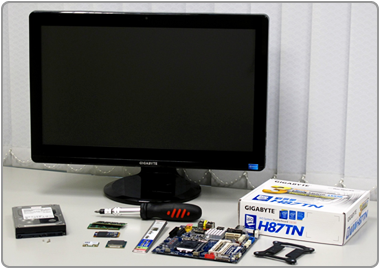
Here is a list of the components that we used to construct our All-in-One PC. |
-
1 GIGABYTE H87TN Motherboard
-
1 4th generation Intel® Core™ Processor
-
1 Kingston mSATA SSD
-
2 x 2GB Transcend SO-DIMM DDR3 Memory Modules
-
1 Atheros AR5B22 Mini PCI-E wireless network card (802.11a/b/g/n and Bluetooth 4.0)
-
1 Thin Mini-ITX-compliant chassis with integrated LED touch screen display
Note: The CPU heatsink and fan are supplied with the chassis and are specific to that chassis design. Some chassis manufacturers may specify certain limitations regarding CPU model compatibility due to thermal design constraints. |
|
| |
|
|
| |
Installation |
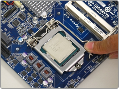
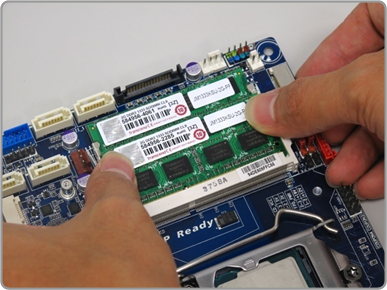
Step 1 – Install CPU and Memory
First we need to install the CPU in the motherboard socket as per the standard CPU mounting procedure for all socket 1150 CPUs, paying particular attention to not damage or bend the socket pins. Thin Mini-ITX specifies smaller SO-DIMM DDR3 modules. These simply click into place and are securely held by latches on either side of the module.
|
| |
|
|
|
| |
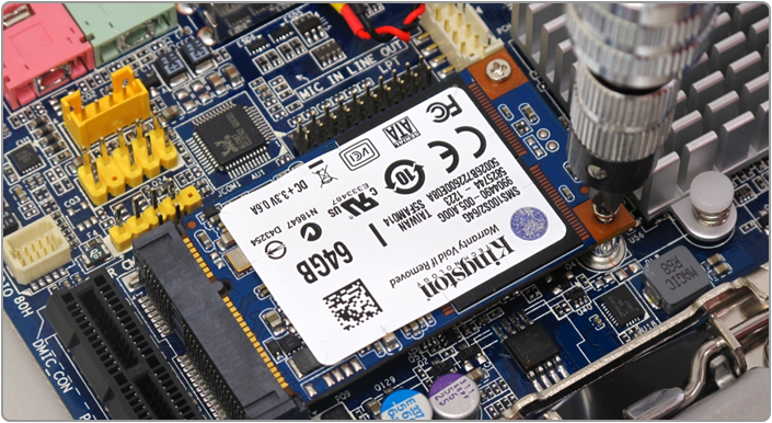
Step 2 – Installing the mSATA SSD
GIGABYTE Thin Mini-ITX motherboards support an mSATA slot for easy integration of an mSATA SSD module. Designed to host the PC’s OS, an mSATA SSD provides a fast and responsive PC experience while also requiring very little space and zero cabling. The mSATA SSD simply slots into place and is then be held securely with two small screws. Some chassis designs may also support either 2.5” or 3.5” hard disk drives for additional data storage. Some designs may also integrate a thin DVD drive bay. These can be added to the system via the onboard SATA ports.
|
|
|
|
|
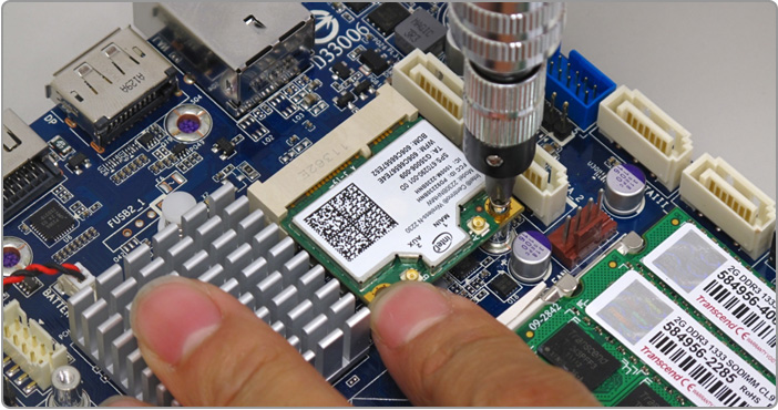
Step 3 – Installing the WiFi/Bluetooth Module
The 3rd step involves installing the Mini-PCIe WiFi/Bluetooth module. GIGABYTE Thin Mini-ITX support a half height Mini-PCIe slot which supports a range of network and communications modules. In similar fashion to the mSATA slot, the Mini PCIe module sits in the slot held in place by two small screws.
|
| |
| |
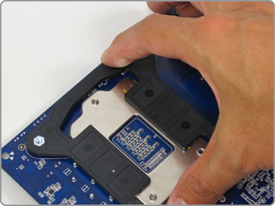
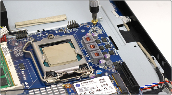
Step 4 – Installing the I/O shell and CPU Cooler Pedestal
Before mounting the motherboard into the chassis, we need to install the I/O shield and also the back plate which will hold the integrated CPU cooler securely in place.
|
|
|
|
| |
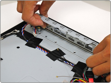
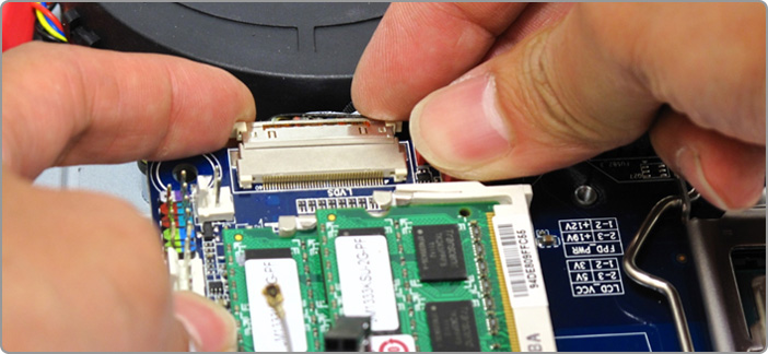
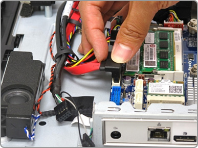
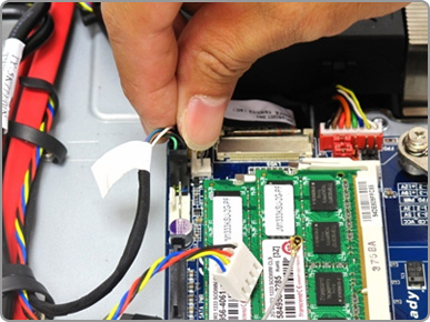
Step 5 – Connecting the LVDS Display and Installing the GIGABYTE Thin Mini-ITX Motherboard
Before the motherboard is securely installed within the chassis we need to connect the PC’s display first. A thin LVDS connector is standard for Thin Mini-ITX AIO builds and should be found already connected to the display inside the chassis. As you can see in the image below, the LVDS connector then attaches to a port on the side of the motherboard. Make sure that the LVDS connector is connected correctly. Connecting the LVDS connector the wrong way could cause a short circuit.
|
|
| |
Next we can install the Thin Mini-ITX motherboard inside the chassis. As with all Mini-ITX specification motherboards, the board is installed by using four small screws that are located in each of the board’s four corners.
|
|
| |
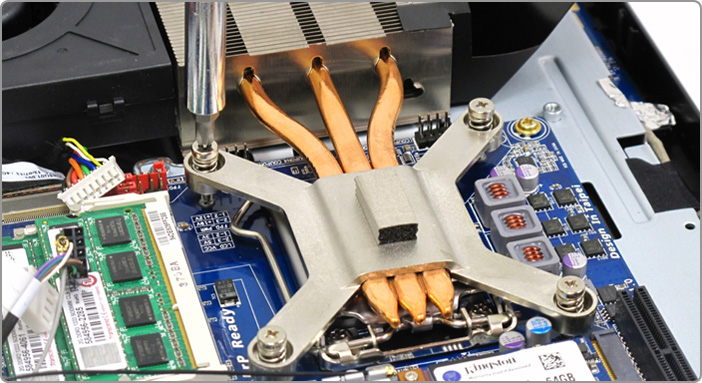
Step 6 – Installing the Heatsink and Cooling Fan
Next we need to install the CPU heatsink and cooling fan. The exact design of the heatsink and fan will vary by chassis model, but the guiding principles will be the same for each chassis. In the example shown below, the heatsink is firmly attached to the board over the CPU socket, ensuring a good contact between the CPU and the heatsink which is then connected to the fan by copper tubing. The fan is located on the edge of the chassis allowing hot air to be expelled from the PC.
|
|
|
| |
Step 7 – Connecting all the cables
Once the heatsink installation is complete, we can connect all the remaining cables to the motherboard, these include both power and data SATA cables.
|
|
| |
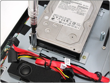
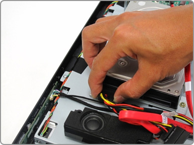
Step 8 – Installing more storage device
Some chassis designs may also support either 2.5” or 3.5” hard disk drives for additional data storage. After the motherboard and all cables are installed, you can install the larger 3.5” hard drive, which is secured in place using four small screws, then connected to the board using SATA cables.
|
|
|
|
| |
|
|
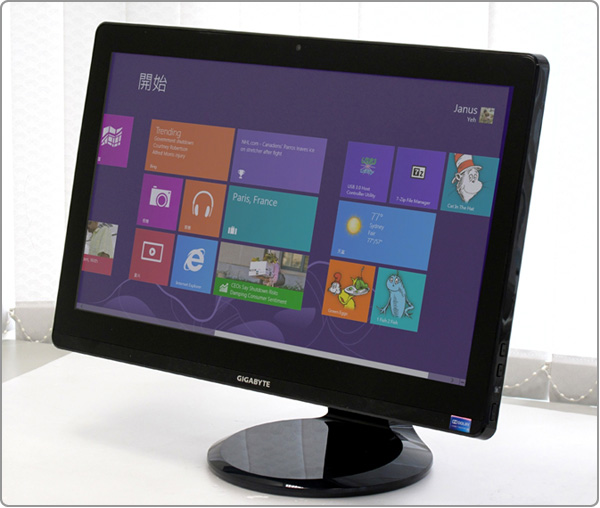
Once the hardware installation is complete, the chassis back panel can be re-mounted and secured. Now we are ready to install the OS – Windows 8 would certainly seem to be a good fit for any All-in-One PC that features a touch capable display.
|
|
| |
|
|
|
|