 |
7-1 |
Connect cables to internal connectors and headers on the motherboard, including IDE/SATA connectors, and front panel audio, USB, IEEE 1394 headers, etc. |
| |
7-2 |
Attach the front panel module (differs depending on the case design, consisting of power indicator, hard drive activity indicator, speakers, reset switch, power switch, etc.) from the case to the front panel header (F_PANEL) on the motherboard. |
| |
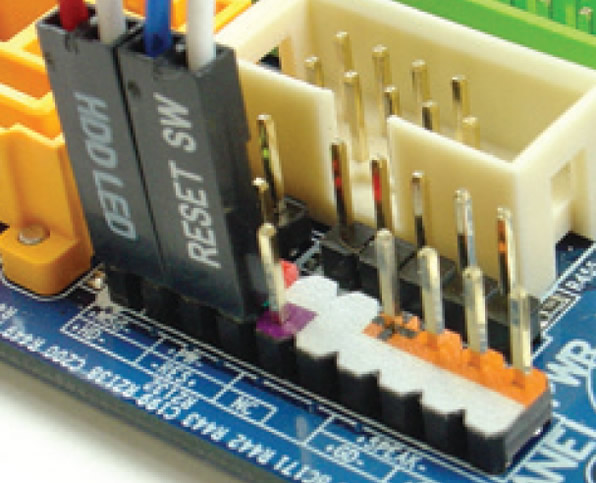 |
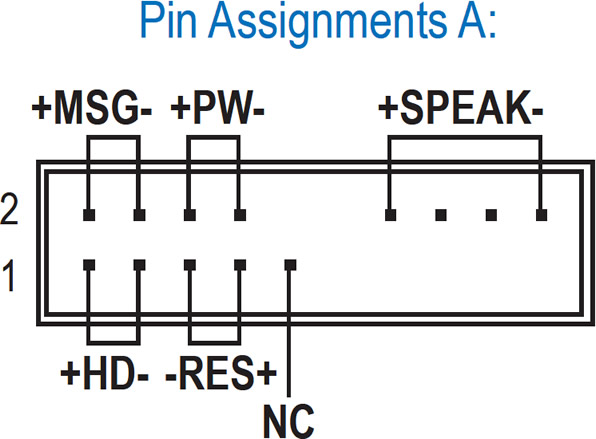
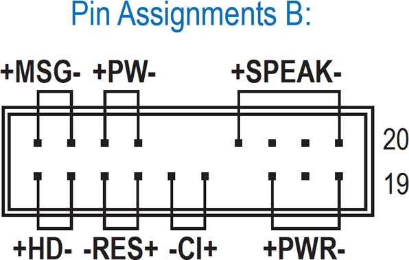
Front Panel Header |
| |
 |
| |
 |
| |
MSG: Message/Power/Sleep LED
PWR: Power LED
PW: Power Switch
SPEAK: Speaker
HD: Hard Drive Activity LED
RES: Reset Switch
CI: Chassis Intrusion Header |
| |
Note
|
The pin assignments for the front panel header may differ by model. Refer to the motherboard user's manual for the actual pin assignments.
|
| |
|
|
| |
|