| Description | Version | Size | Date |
|---|
1/8

H263-V60-LAW1
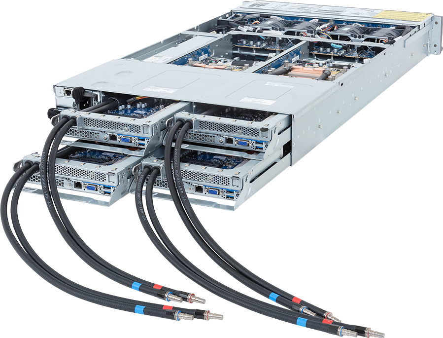
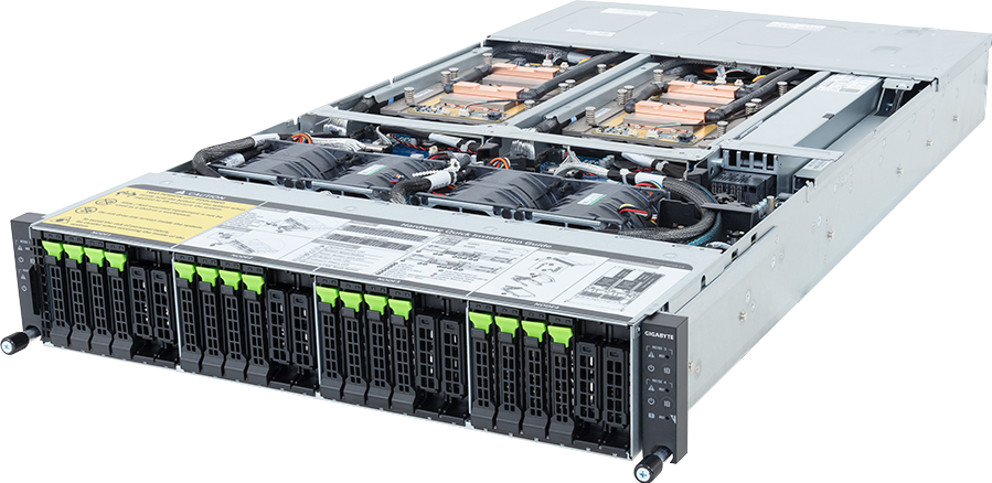
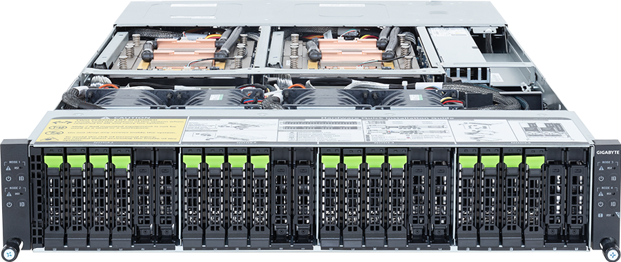
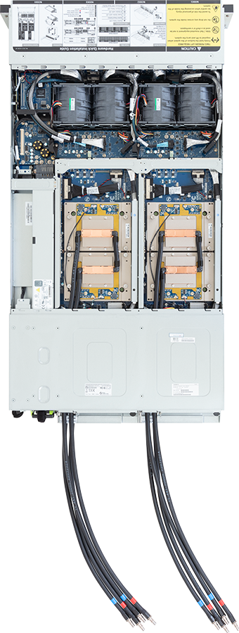
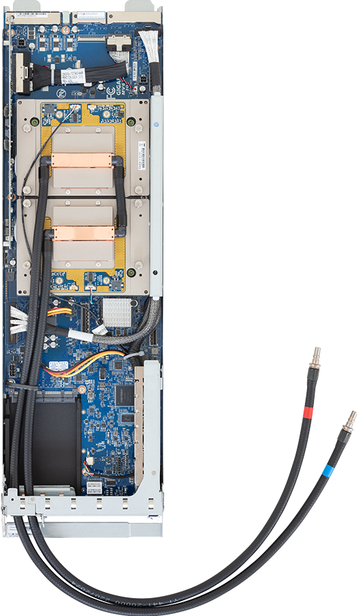
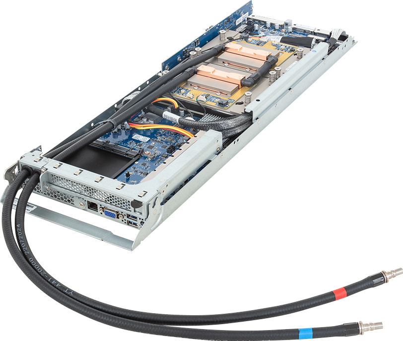
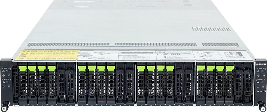
High Density Arm Server - NVIDIA Grace™ CPU Superchip - 2U 4-Node 16-Bay Gen5 NVMe DLC
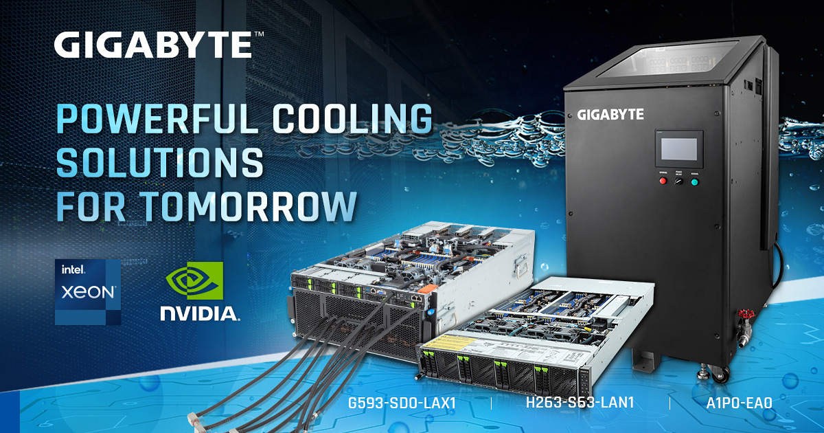
- Direct liquid cooling solution with leak detection
- High-performance CPU for HPC and cloud computing
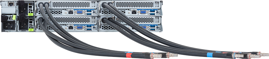
- 2U 4-node rear access server system
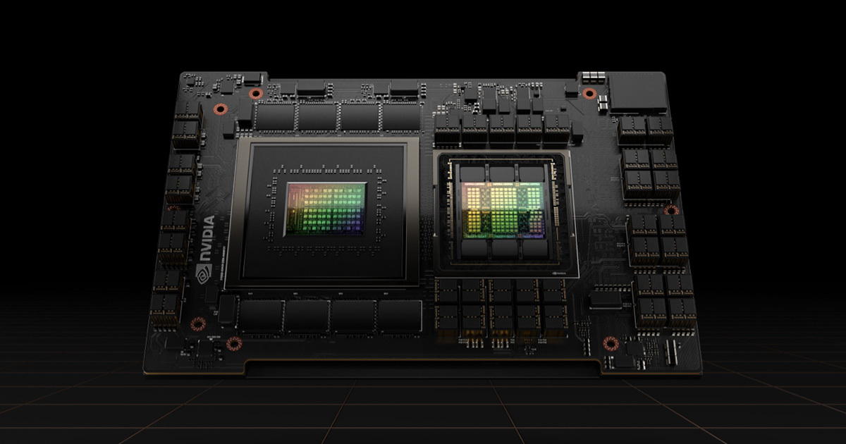
- NVIDIA Grace™ CPU Superchip
- 900GB/s NVIDIA NVLink™-C2C Interconnect
- Up to 960GB LPDDR5X ECC memory per module
- Compatible with NVIDIA® BlueField®-3 DPUs
- 16 x 2.5" Gen5 NVMe hot-swap bays
- 8 x M.2 slots with PCIe Gen5 x4 interface
- 4 x FHHL PCIe Gen5 x16 slots
- 4 x OCP NIC 3.0 PCIe Gen5 x16 slots
- 2+1 3000W 80 PLUS Titanium redundant power supplies
Ordering Numbers: 6NH263V60MR000LAW1*

Specifications
Dimensions (WxHxD, mm)
2U 4-Node - Rear access
440 x 87.5 x 850
440 x 87.5 x 850
Motherboard
MV63-HD0
Superchip
Per node:
NVIDIA Grace™ CPU Superchip:
- 2 x NVIDIA Grace™ CPUs
- Connected with NVIDIA NVLink™-C2C
- TDP up to 500W (CPU + memory)
NVIDIA Grace™ CPU Superchip:
- 2 x NVIDIA Grace™ CPUs
- Connected with NVIDIA NVLink™-C2C
- TDP up to 500W (CPU + memory)
Memory
Per node:
480GB of LPDDR5X memory with ECC [1]
Memory bandwidth up to 1TB/s [1]
[1] Modules with 960GB of CPU memory and 768GB/s memory bandwidth are also available. Please contact our sales representatives for more details.
480GB of LPDDR5X memory with ECC [1]
Memory bandwidth up to 1TB/s [1]
[1] Modules with 960GB of CPU memory and 768GB/s memory bandwidth are also available. Please contact our sales representatives for more details.
LAN
Rear:
4 x 10/100/1000 Mbps Management LAN
1 x CMC Management LAN
4 x 10/100/1000 Mbps Management LAN
1 x CMC Management LAN
Video
Integrated in ASPEED® AST2600 x 4
- 4 x VGA ports
- 4 x VGA ports
Storage
Front hot-swap:
16 x 2.5" Gen5 NVMe
- (8 x NVMe from CPU_0, 8 x NVMe from CPU_1)
Internal M.2:
8 x M.2 (2280/22110), PCIe Gen5 x4, from CPU_1
16 x 2.5" Gen5 NVMe
- (8 x NVMe from CPU_0, 8 x NVMe from CPU_1)
Internal M.2:
8 x M.2 (2280/22110), PCIe Gen5 x4, from CPU_1
SAS
N/A
RAID
N/A
PCIe Expansion Slots
PCIe Cable x 4:
- 4 x FHHL x16 (Gen5 x16), from CPU_1
4 x OCP NIC 3.0 (Gen5 x16), from CPU_0
- Support NCSI function
- 4 x FHHL x16 (Gen5 x16), from CPU_1
4 x OCP NIC 3.0 (Gen5 x16), from CPU_0
- Support NCSI function
Front I/O
4 x Power buttons with LED
4 x ID buttons with LED
4 x Reset buttons
4 x System status LEDs
1 x CMC status LED
1 x CMC reset button
4 x ID buttons with LED
4 x Reset buttons
4 x System status LEDs
1 x CMC status LED
1 x CMC reset button
Rear I/O
8 x USB 3.2 Gen1 ports (Type-A)
4 x VGA ports
4 x MLAN ports
4 x ID buttons with LED
1 x CMC port
4 x VGA ports
4 x MLAN ports
4 x ID buttons with LED
1 x CMC port
Backplane Board
Speed and bandwidth:
PCIe Gen5 x4
PCIe Gen5 x4
Security Modules
1 x TPM header with SPI interface
- Optional TPM2.0 kit: CTM012
- Optional TPM2.0 kit: CTM012
Power Supply[#1]
2+1 3000W 80 PLUS Titanium redundant power supplies [1]
AC Input:
- 100-127V~/ 16A, 50/60Hz
- 200-207V~/ 16A, 50/60Hz
- 208-240V~/ 16A, 50/60Hz
DC Input: (Only for China)
- 240Vdc/ 16A
DC Output:
- Max 1200W/ 100-127V~
+12.2V/ 98.36A
+12.2Vsb/ 3A
- Max 2600W/ 200-207V~
+12.2V/ 213A
+12.2Vsb/ 3A
- Max 3000W/ 208-240V~ or 240Vdc Input
+12.2V/ 245.9A
+12.2Vsb/ 3A
[1] The system power supply requires C19 power cord.
System Management
ASPEED® AST2600 Baseboard Management Controller
ASPEED® AST2520 Chassis Management Controller
GIGABYTE Management Console web interface
ASPEED® AST2520 Chassis Management Controller
GIGABYTE Management Console web interface
- Dashboard
- HTML5 KVM
- Sensor Monitor (Voltage, RPM, Temperature, CPU Status …etc.)
- Sensor Reading History Data
- FRU Information
- SEL Log in Linear Storage / Circular Storage Policy
- Hardware Inventory
- Fan Profile
- System Firewall
- Power Consumption
- Power Control
- Advanced power capping
- LDAP / AD / RADIUS Support
- Backup & Restore Configuration
- Remote BIOS/BMC/CPLD Update
- Event Log Filter
- User Management
- Media Redirection Settings
- PAM Order Settings
- SSL Settings
- SMTP Settings
System Fans
4 x 80x80x80mm
Operating Properties
Operating temperature: 10°C to 35°C
Operating humidity: 10% to 80% (non-condensing)
Non-operating temperature: -40°C to 60°C
Non-operating humidity: 20% to 90% (non-condensing)
[Note] To ensure system stability and prevent condensation, when the relative humidity exceeds 50%, the coolant inlet temperature must be higher than the dry-bulb temperature and it should not exceed 45°C.
Weight
Net Weight: 49.37 kg
Gross Weight: 54.37 kg
Gross Weight: 54.37 kg
Packaging Dimensions
1181 x 715 x 336 mm
Packaging Content
1 x H263-V60-LAW1
4 x Superchip cold plate loops
1 x 3-Section Rail kit
4 x Superchip cold plate loops
1 x 3-Section Rail kit
Part Numbers
- Barebone with NVIDIA module: 6NH263V60MR000LAW1*
- Motherboard: 9MV63HD0UR-000*
- 3-Section Rail kit: 25HB2-A66125-K0R
- Superchip cold plate loop: 25ST7-3000Z8-C4R
- Front panel board - CFPH004: 9CFPH004NR-00*
- Backplane board - CBPH7O1: 9CBPH7O1NR-00*
- Fan module: 25ST2-888020-S1R
- M.2 riser card - CMTP0A2: 9CMTP0A2NR-00*
- LAN board - CLBH010: 9CLBH010NR-00*
- Leak sensor board - CDB92: 9CDB92NR-00*
- Power supply: 25EP0-230009-L0S
Optional parts:
- GIGABYTE Superchip cold plate loop: 25H26-3V60000-E43X (QPA:4)
- GIGABYTE 2U4N Manifold: 25H27-3Z80000-E07X (1 set per rack)
[#1] Power cords are not included with server packages. Customers are responsible for selecting appropriate power cords from the optional accessories or contacting sales for customization.
[#2] All materials provided herein are for reference only. GIGABYTE reserves the right to modify or revise the content at any time without prior notice.
[#3] Advertised performance is based on maximum theoretical values as specified by the respective chipset vendors or standards organizations. Actual performance may vary depending on system configuration.
[#4] All trademarks and logos are the property of their respective owners.